

Our design consists of four 3D printed components: superior guide, acetabular support, hand guide, and indicator rod. The fifth component is a tool commonly employed in surgeries, which are Steinmann pins.
SUPERIOR GUIDE
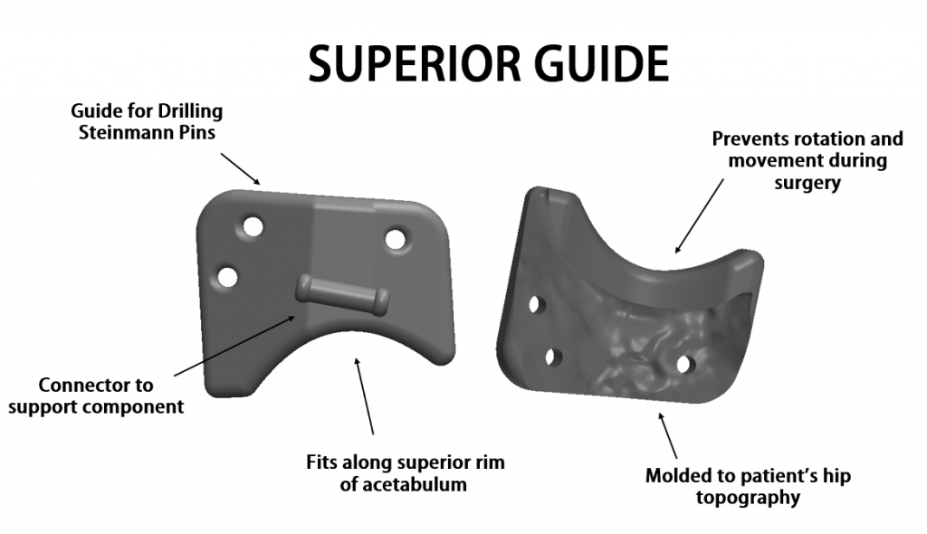
The superior guide is molded to the superior region above the acetabulum on a patient’s pelvis. It is also molded around the acetabular rim for a close fit without any rotational or translational movements possible. This component guides the placement for three Steinmann pins to be inserted into the patients hip.
ACETABULAR SUPPORT
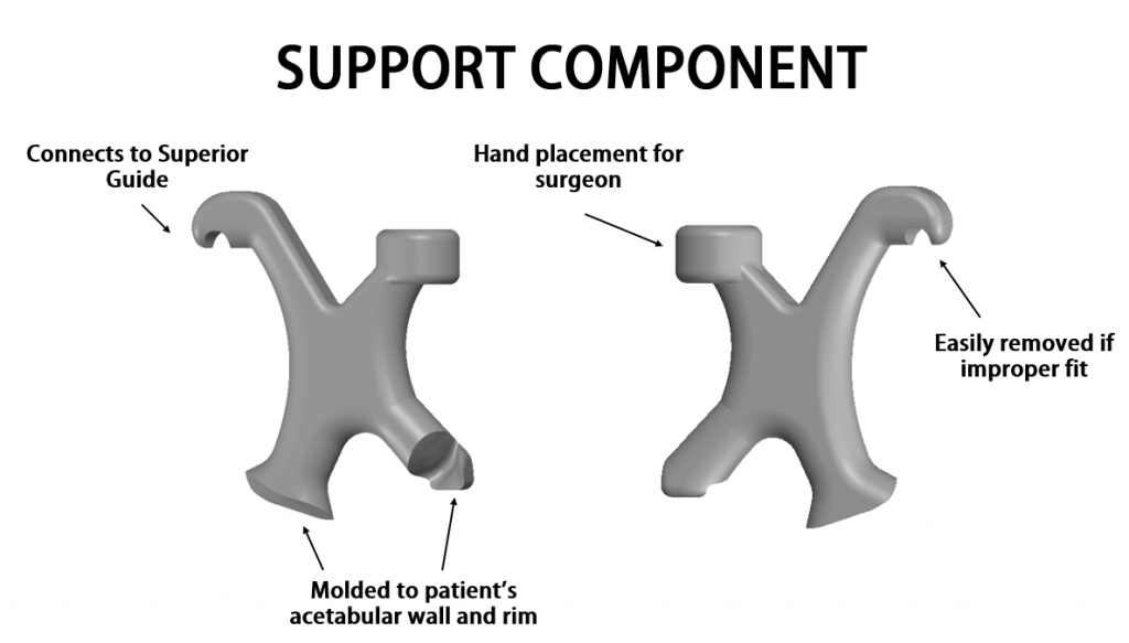
The acetabular support component latches on to the superior component and rests on the acetabulum floor and the rim. This component acts as a check to ensure the superior component is correctly positioned and provides the surgeon with a hand support during the Steinmann pin placement.
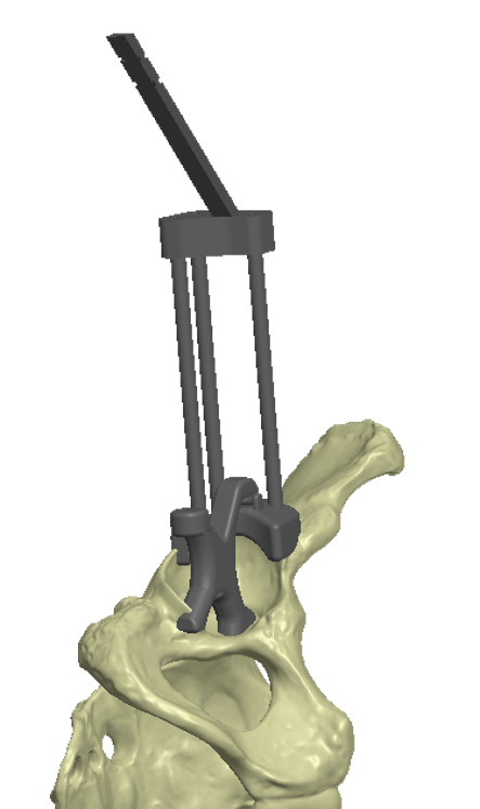
HAND GUIDE & INDICATOR ROD
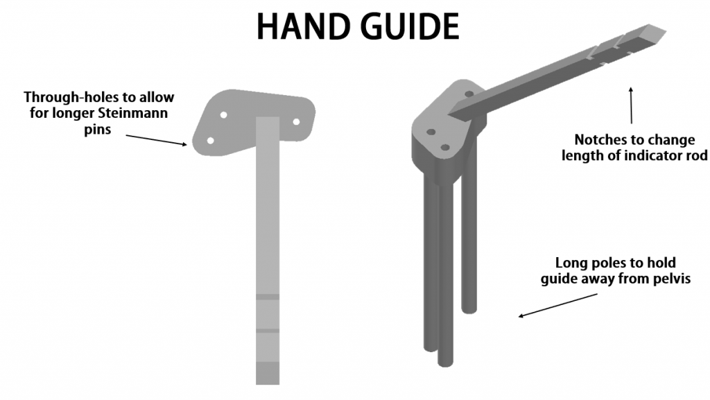
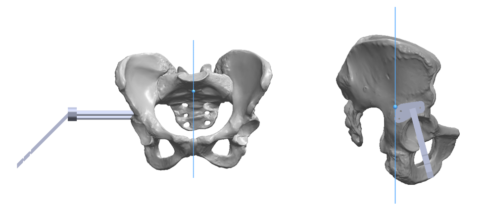
Once the superior and acetabular support components are removed, the hand guide is then slid over the three Steinman pins. The indicator rod extending from the hand guide provides a visual representation for the surgeon of the correct abduction and anteversion angles. The indicator rod is out of the way of the surgeons working view; however, still provides them the ability to visually align their tools.
REQUIREMENTS
