The final design for the project was a Siemens Programmable Logic Controller (PLC) system. This is a small industrial automation device, commonly used to control large electrical systems such as lighting and air control in department stores or large piping networks. The controller is fully programmable and adaptable to countless applications. Our system required that the controller collect data continuously from the dynamometer sensors, while still prioritizing the user commands recognized by the external touch screen. This means that the user can simply set the test velocity and start the test and the controller program will automatically conduct the test and collect data unless the test is interrupted by a user input or a safety switch.
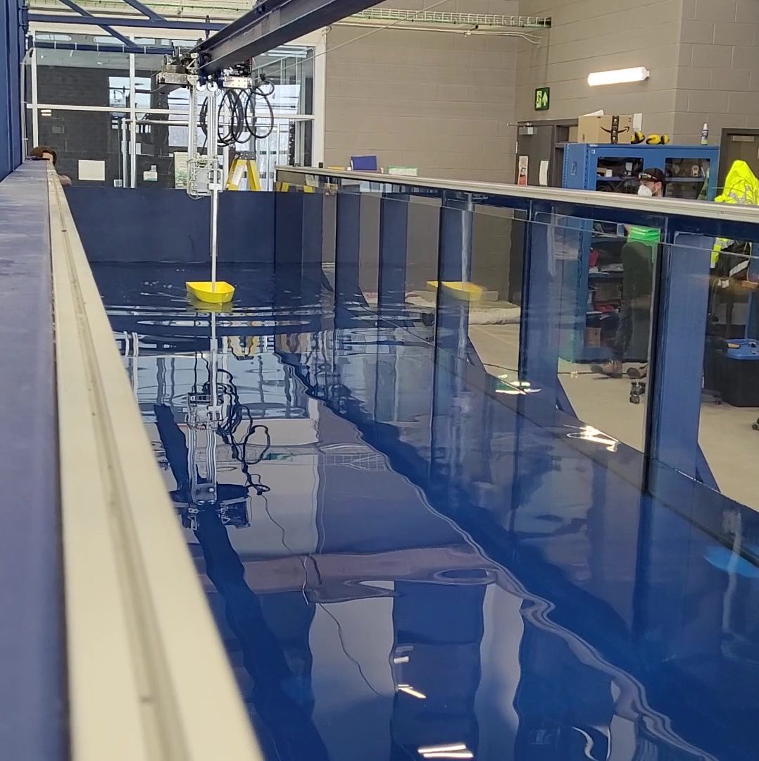
Using the Tow Tank
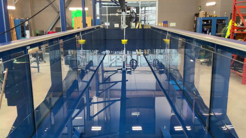
The tow tank begins each test from the home position at the bottom end of the tank.
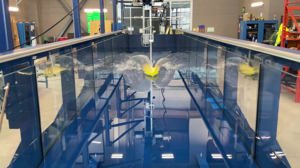
Once the user starts the test from the system touch screen, the motor then tows the dynamometer down the tank. The dynamometer sensors begin collecting data once the model hull reaches a steady, constant speed.
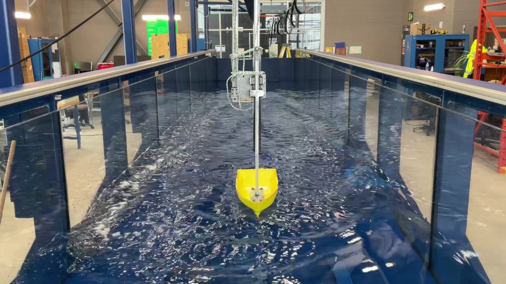
Once the model boat reaches a specified distance from the end of the tank, the motor is stopped and the boat is brought to a halt. The data from the test is then exported from the system and the motor automatically tows the model hull back to the starting position, ready for another test.
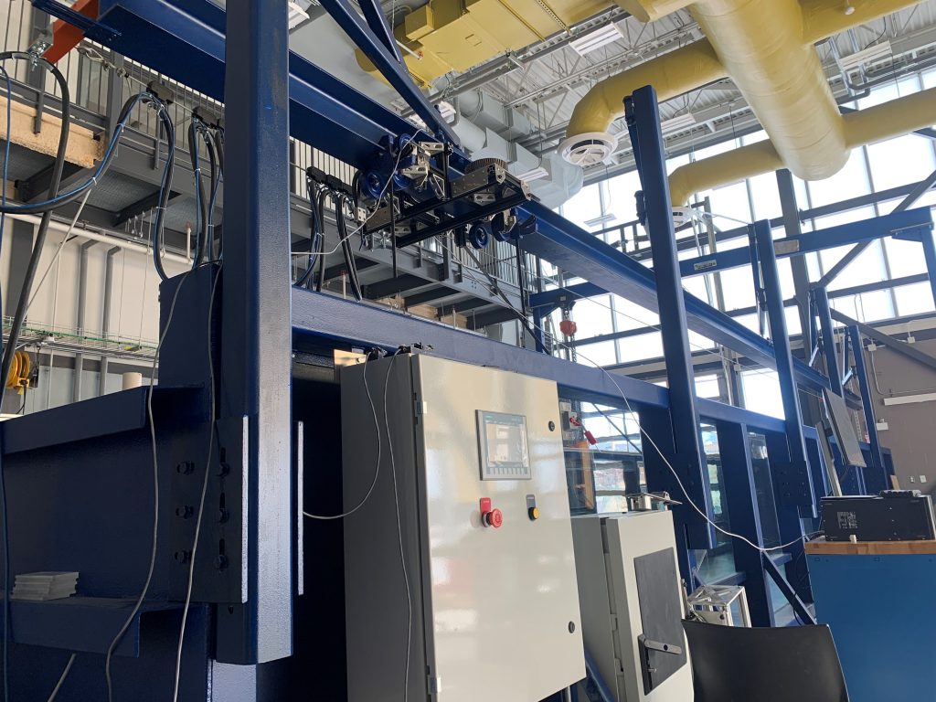
The PLC Cabinet
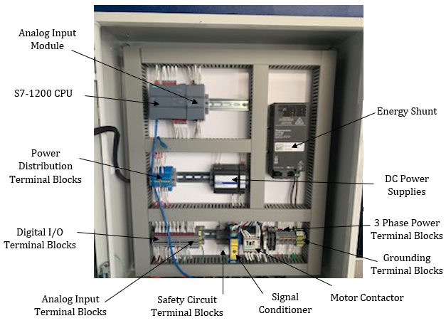
Inside the PLC cabinet you can see the vital components of the control system.
- The S7-1200 CPU is the systems PLC. This is where the whole system is controlled from, where the program is uploaded and stored, and where test data is read and transmitted.
- The analog input module: allows the system to read measurements in a range of values instead of 1 or 0. This includes the pitch, yaw, heave, and sway of the model hull.
- The safety circuit terminal blocks allow for easy power cutoff to the system is the emergency stop is pressed or one of the emergency limit switches is triggered.
The Limit Switches
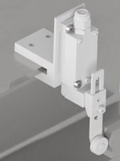
To allow the program controller to know where the model boat hull is in the tank, four limit switches were installed in the system. Limit switches are switches that detect contact. When a force is applied to the wheel, the switch stops power flow through it.
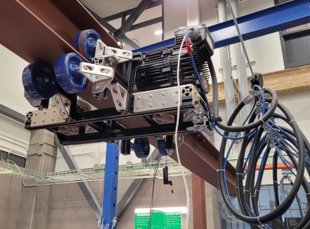
The motor carriage moves along a beam. the four limit switches are positioned on the beam so that the arm is tripped by the carriage when it reaches it.
Bringing the System Together
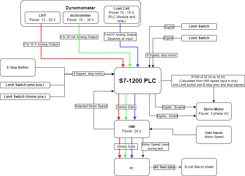
Bellow is a diagram which shows the roles and relationships of all of the components of this project.